Social

Social

Social

Friday, December 2, 2016

Facebook Authentication in Ruby on Rails

Goal:  Make my site easier for vistors by allowing them to register or login (existing Devise account) with Facebook.

I have Rails 4.2, Devise 4.2

I mostly follow the this Devise how-to for setting up OmniAuth:
https://github.com/plataformatec/devise/wiki/OmniAuth:-Overview


Exceptions to above how-to:

in devise.rb initializer I added

 # added this for facebook authentication
  if Rails.env == "production"
    fb_callback = "https://www.mylivesite.com/users/auth/facebook/callback" 
  else 
    fb_callback = "http://localhost:3000/users/auth/facebook/callback" 
  end
  config.omniauth :facebook, ENV['AD_FB_APP_ID'], ENV['AD_FB_APP_SECRET'],
                callback_url: fb_callback ,
                info_fields: 'name,email'
The environment variables are
AD_FB_APP_ID and AD_FB_APP_SECRET I set these in my local machine's bashrc file (ubuntu linux installed) to match the values in my newly created facebook app.


my projects are located under /home/sean/projects, so when I am in a specific project directory I edit bashrc like:

nano ../../.bashrc

re-read bashrc after saving:  source ../../.bashrc

Facebook App Dashboard


Facebook settings are tricky. Within https://developers.facebook.com/apps/xxxxxxxxxxxxxxx/dashboard/


Add Facebook Login product


Then Set 'Valid OAuth redirect URIs' to:

http://localhost:3000 and https://www.mylivesite.com


Under Settings: Add 'website' platform, then set app domains to www.mylivesite.com

Under App Review: make live


User Methods


After following along with the rest of the devise tutorial above, I came up with the following two methods for my user model:
  def self.from_omniauth(auth)
    user = User.find_by(email: auth.info.email)
    # https://github.com/plataformatec/devise/wiki/How-To:-Add-:confirmable-to-Users
    if user and user.confirmed? 
      user.provider = auth.provider
      user.uid = auth.uid
      return user
    end
    #where(auth.slice(:provider, :uid)).first_or_create do |user|
    where(provider: auth.provider, uid: auth.uid).first_or_create do |user|
     #user.skip_confirmation! 
      user.provider = auth.provider
      user.uid = auth.uid
      user.email = auth.info.email
      user.password = Devise.friendly_token[0,20]
      user.first_name = auth.info.name.split(" ")[0..-2].join(" ")
      user.last_name = auth.info.name.split(" ").last
      #user.first_name = first_name
      #user.last_name = last_name
    end
  end

  def self.new_with_session(params, session)
    super.tap do |user|
      if data = session["devise.facebook_data"] && session["devise.facebook_data"]["extra"]["raw_info"]
        user.email = data["email"] if user.email.blank?
        user.first_name = data["name"].split(" ")[0..-2].join(" ") if user.first_name.blank?
        user.last_name = data["name"].split(" ").last if user.last_name.blank?
      end
    end

  end

I am using Heroku so I need to remember to set the Facebook app key and secret variables in my Heroku settings as well

Update


I realized I need users to finish filling out their registration form to get info that facebook does not provide such as phone.  However, since the password was auto generated for them on registration with facebook, I need a way to get the additional info and not bother them for a password in the process (which they do not know).

First I redirect the new signup to the registration page:
I edit my omniauths_callbacks_controller.rb

class Users::OmniauthCallbacksController < Devise::OmniauthCallbacksController
  def facebook
    # You need to implement the method below in your model (e.g. app/models/user.rb)
    @user = User.from_omniauth(request.env["omniauth.auth"])
    if @user.persisted?
      sign_in @user

      # there is probably a better way to do this but I need to get new accounts to finish registration
      if @user.created_at > Time.now - 1.minute 
        redirect_to edit_user_registration_url 
        flash[:alert] = "Please set phone.  Choose texting preference if desired."
      else
        redirect_to root_url

      end

      #sign_in_and_redirect @user, :event => :authentication #this will throw if @user is not activated
      set_flash_message(:notice, :success, :kind => "Facebook") if is_navigational_format?
       flash[:alert] = "Please set phone.  Choose texting preference if desired."
    else
      session["devise.facebook_data"] = request.env["omniauth.auth"]
      redirect_to new_user_registration_url
    end
  end

  def failure
    redirect_to root_path
  end
end

Then, I add a new controller under controllers/users/registrations_controller.rb:

class Users::RegistrationsController < Devise::RegistrationsController
  # allow facebook registrations to edit account without password
  # http://stackoverflow.com/questions/13436232/editing-users-with-devise-and-omniauth

  def update_resource(resource, params)
    resource.update_with_password(params)
  end

  # Overwrite update_resource to let users to update their user without giving their password
  def update_resource(resource, params)
    if resource.provider == "facebook"
      params.delete("current_password")
      resource.update_without_password(params)
    else
      resource.update_with_password(params)
    end
  end
end

I add a route for it in routes.rb like so:

devise_for :users, :controllers => { :omniauth_callbacks => "users/omniauth_callbacks", :registrations => 'users/registrations' }

Lastly, I hide the password fields on my views/devise/registrations/edit.html.rb form by wrapping all three of the password fields with

<% if (!current_user.provider=='facebook') %>

<% end %>

Thursday, August 4, 2016

Live Streaming to Youtube with Raspberry Pi 3

After a bit of research on the best way to stream from the Raspberry Pi 3 with camera sensor version 2, I came across this tutorial:
https://www.raspberrypi.org/forums/viewtopic.php?f=63&t=134141&p=893318#p893318

So I followed this until I hit issues.

When compiling ffmpeg for Raspberry Pi 3 I want to use all four cores of processor.

Where these instructions ( http://www.valmueller.net/stream-video-with-raspberry-pi-to-youtube/ ) say:

sudo make
sudo make install

I replaced it with:
sudo make -j4 install
Testing the install of ffmpeg:
ffmpeg

gives this error:
/usr/local/bin/ffmpeg: cannot execute binary file: Exec format error

I noticed that my full version of jessie must have had ffmpeg in it already so I removed it but it did not help:

I did not note the exact way I removed it but it was something like:
sudo apt-get remove ffmpeg

I removed the ffmpeg directory I had previously cloned ( /usr/src/ffmpeg) and cloned from another source:
https://git.videolan.org/git/ffmpeg.git

Then rebuilt with no options to see what happened:
sudo ./configure
sudo make -j4 install

then ran stream on command line and it worked!
sudo raspivid -o - -t 0 -w 1280 -h 720 -fps 25 -b 4000000 -g 50 | ffmpeg -re -ar 44100 -ac 2 -acodec pcm_s16le -f s16le -ac 2 -i /dev/zero -f h264 -i - -vcodec copy -acodec aac -ab 128k -g 50 -strict experimental -f flv rtmp://a.rtmp.youtube.com/live2/my-utube-code-here

But while steaming I did get some warnings and errors to investigate further:

Using AVStream.codec to pass codec parameters to muxers is deprecated, use AVStream.codecpar instead.

[flv @ 0x16dba70] Timestamps are unset in a packet for stream 0. This is deprecated and will stop working in the future. Fix your code to set the timestamps properly
[h264 @ 0x168e1f0] Thread message queue blocking; consider raising the thread_queue_size option (current value: 8)
^Cmmal: Aborting program.0 size= 56962kB time=00:04:02.11 bitrate=1927.3kbits/s speed= 1x

[flv @ 0x16dba70] Failed to update header with correct duration.
[flv @ 0x16dba70] Failed to update header with correct filesize.

Youtube showed my live stream with a starting delay and a status of 'healthy' in green.
Raspberry Pi v2  with alternative pi-compatible camera module .  Camera sensor is v1 based 5 megapixel with adjustable focus and near fish eye - around 160 degrees angle of view

Next I can now investigate the errors and consider recompiling my ffmpeg with some of the options if needed.

UPDATE:
After some time playing with video, I resolved jerky capturing and added text display with this new run string

 sudo raspivid -o - -t 0 -w 1280 -h 720 -fps 30 -ex sports -b 4000000 -g 50 -a 12 -ae 10,0x00,0x8080ff -a "My Camera %m-%d-%y @ %I:%M %P" | /usr/src/ffmpeg/ffmpeg -re -ar 44100 -ac 2 -acodec pcm_s16le -f s16le -ac 2 -i /dev/zero -framerate 30 -f h264 -i - -vcodec copy -acodec aac -ab 128k -g 60 -strict experimental -f flv rtmp://a.rtmp.youtube.com/live2/my-youtube-id

Friday, February 26, 2016

Worm Bin Moisture Sensor with Arduino

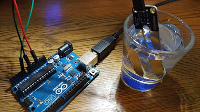
Arduino connected to Rapsberry Pi with USB
Arduino Uno with analog moisture sensor and usb connected to Pi


I have my worm bin temperature sensors working very well with my Raspberry Pi.  I have now turned my attention to measuring soil moisture.

Moisture Sensing Choices:

  • Which soil moisture sensor should I use?
  • Which micro controller do I employ?
  • How many sensors are needed for practical use?

After a lot of searching for sensors, it seems that moisture sensing is not nearly as straightforward  as reading air or soil temperatures.  There are different ways of reading moisture.

I honestly do not know the ideal way to read moisture. It seems that measuring the electrical conductivity of the soil to look for moisture is a popular method so I will go with that.

Sensor Corrosion Problem

One significant problem with sensors using electrical resistance is that they do not last very long because they corrode due to the electricity and metal contacting wet soil.  To help minimize this issue, you can get them gold plated and only power the sensor before you take your reading and then turn it off to maximize sensor contact life.

Note: I am a noob regarding electrical things but it looks like I might be able to control power to the sensor with a transistor (It acts as an electronic switch).

I opted to go with a quick-and-dirty approach first.  The Raspberry Pi has no analog pins to read and write to.  Moisture sensors require analog connections to the microcontroller to work.  After all, 0 and 1 tell you wet or dry but no values in between.

The sensor I bought first is http://amzn.to/1Q68YSW

I happen to have an Arduino Uno that I played with a few years back, so its time to dust it off  and put to work.  Actually, my board is revision 3 which looks current.  

I proceed to install the Arduino ide and make sure it works with a few simple LED light blinking sketches.  All good so far.

My moisture sensor arrives from Amazon and I realize it has absolutely no documentation so I start googling what is printed on it "ywRobot mositure sensor" and come across some schematics and this helpful video... (it's actually wRobot I think)


I follow along with the video and within a couple of minutes I have it reading values 0.  I drop it into a shot glass of water and the reading changes to around 600 give or take.


Setup Raspberry Pi to Log Serial Data 

(That is send moisture readings via USB from your Arduino sketch to Pi)


Make sure Python is installed on Pi.  

You can attempt to install or check version.
install:
sudo apt-get install python 
or check python version:
python -V

Install moreutils... 

to get TS (time stamp) package.  moreutils is a basic linux grouping of hand features not included in standing linux distribution.

sudo apt-get install moreutils

Install grabserial

grabserial is a utility to read serial data from serial port of remote linux microcontroller and write to standard out (like a text file for later use).

wget https://github.com/tbird20d/grabserial/blob/master/grabserial


Test serial (USB) connection

lsusb

I see all the usb connected devices including my arduino:
Bus 001 Device 004: ID 2341:0043 Arduino SA Uno R3 (CDC ACM)

Get device id
This is a little tricky.  I used grep to get keyword related results since my results spanned multiple pages:

dmesg | grep tty
I looked through results and found my id of TTYACM0
You can just page through results with:
dmesg | more

Incidentally, the /dev directory is a listing of hardware devices and those prepended with 'tty' are serial devices.

NOTE: the symbol | is typed by using shift : on your keyboard.  It's called a pipe command.

Configure grabserial to use the correct serial port

use the text editor nano (You can us vi and others but vi has a steeper learning curve.):  
nano grabserial

within the file use the ctrl-w command to jump right to the lines to configure.  Search for 'sd.port' (which takes your down about 7 pages).

Change your setting to match your serial port id found in dmesg:

        sd.port="/dev/ttyACM0"
        sd.baudrate=9600

You are setting the baud rate to match what your arduino serial port was set to in the sketch you installed.

Within grabserial file save with CTRL-x to exit and Y to save changes.

Check that grabserial is working:

python grabserial

I get output:
  , 0
because my sensor is not in water so all works and I CTRL-c to stop.

to get the timestamp for each reading

python grabserial | ts
Feb 14 16:53:26  , 0


Permanently Log Moisture Readings

There are a lot of ways to process the data now.  You can save to database or save to text (csv) file.  You can then use a web page to display, chart, or export to your computer to use in excel or your favorite charting program.

To write the data to a csv file for use later with use:
python grabserial | ts  >  moisture.csv 

To add a new data file in our sensor directory (to chart with the other sensors):
python grabserial | ts  >  /home/pi/projects/temp-and-humidity/sensor-values/moisture.csv

or even better yet, run the command above with a cron job then edit the worm bin web page to read the data (/home/pi/projects/temp-and-humidity/public/index.html)   You can check this crontab tutorial for more info on doing this.

Using Raspberry Pi Only

In this post I am using the Arduino because the Raspberry Pi does not come with analog pins and I did not have a spare Raspberry Pi lying around.  However, there is a way to use analog devices with Raspberry Pi using an analog to digital controller (ADC).  I will explore that in another post.

Number of Sensors


I have heard suggestiongs to go with 1 sensor every foot.  In this case, my 3 x 4 ft bin could use 3 sensors.  Once I settle on a platform, I will pickup 2 more sensors, figure out the switchin them on and off method, solder up some long wires to a board, connect them to one of the controllers, and coat the electronics with heat shrink tubing and silicone conformal coating to prevent moisture damage.

Conclusion

You can use any micro controller to read analog inputs.  It may just come down to which platform you are confortable with.  There are major differences in Raspberry Pi (a full computer operating system)  and Arduino (real time microcontroller), but simple analog readings can be done with both platforms.


Saturday, February 20, 2016

Keeping Your Raspberry Pi Connected Via WiFi

Is Your Raspberry Pi Loosing Wifi Connection? 

When my local network's access point or router restarts my Raspberry Pi does not always reconnect to the network.   This can also happen if the Pi's wifi is flaky due to distance or other issues.

To fix this I created a shell script that runs at start up based on this post.

in /home/pi add file:
nano network-monitor.sh

#!/bin/sh -e
while true ; do
   if ifconfig wlan0 | grep -q "inet addr:" ; then
      sleep 60
   else
      echo "Network connection down! Attempting reconnection."
      ifup --force wlan0
      sleep 10
   fi
done
exit 0

I run this script in /etc/rc.local
#!/bin/sh -e
/home/pi/network-monitor.sh &
exit 0

sudo nano /etc/rc.local

Then made sure rc.local was executable:
sudo chown root /etc/rc.local
sudo chmod 755 /etc/rc.local

Make sure rc.local is executable:
sudo chmod +x /home/pi/network-monitor.sh
Check that setting change was made (look for x in permissions of file)
 ls -al /home/pi

Test if it will work in startup:
sudo /etc/init.d/rc.local start

It it works, restart your Pi:
CTRL-C to stop script if needed
sudo reboot

You can further test by restarting your access point or router.

Thursday, February 4, 2016

Worm Bin Monitor Live: Part 3

I am continuing to refine my flow-through worm bin temperature monitoring system.  In part 1 and part 2 I started prototyping what the system would do based on a couple of third party tutorials that I combined.

Worm Bin Up & Running

I am now have everything working in the real world.  To do that I needed

  • a decent wireless network signal outdoors to talk to the system from inside my home
  • more permanent electronic connections so things don't fall apart if moved
  • a bin full of worms
  • mild protection for electronic components


dust-resistant enclosure

Outdoor Wi-fi

I have an indoor wireless access point but it does not get me very far outdoors.  I needed to get good network access at least 250 feet though many large pine trees to monitor anything.  To do this I purchased and installed a wireless access point designed for outdoor use.

I mounted this AP on the outside wall of my second story.  I had my doubts it would work very well, but I was really surprised that it does.

I also boosted the reception of the Raspberry Pi at the worm bin with a USB wireless adapter with an external antenna.  The downside of this particular antenna is that it requires a powered USB hub to stay well connected.

I purchased the EnGenius ens202-ext Outdoor Wireless Access Point and found a powered usb hub on Amazon.  The connection is working great.


Stabilizing The Electronics

In the working photo above, the red circled area is the air temperature and humidity sensor.  The green area is the solder less breadboard I used in previous steps to setup the sensors temporarily.

I had to learn to solder to make it all stable.  I have never soldered so I checked out some how-tos on the subject.  This soldering Instructable got me going.  I was in a hurry so I went down to the local Radio Shack (mine is still in business but has limited supply).

I picked up some 0.35 leaded rosin core solder, a pack of cheap circuit boards, and some 22 gauge solid core wire.  I already had a 25 watt soldering iron I had used years ago for something else.

Soldering takes practice but I was able to recreate my two sensor circuits on a small board.   I removed all the wires and resistors off of the original white breadboard .  I left the breadboard in place so I can add new sensors in the future (soil moisture sensor?).  I soldered wires onto the air sensor (red circle) to extend it outside of the foam box.

My worm bin is outdoors but under cover.  I am not too worried about moisture and dirt but do want some modest protection from dust.  I opted to reuse a foam food container to house the electronics.

Incidentally, these foam boxes are a major sore spot for me because locally all the restaurants hand them out for take out and leftovers.  In California, where I am from, Styrofoam has been illegal for many years.  The southern US is way behind on environmental awareness, so it's nice to re purpose things when I can.

Adding The Worms 

Finally...the worms are added.  I ordered 10K red wigglers online.  They came plump and lively.  I added them to the bin 24 hours ago.  

10 lbs of Eisenia Foetida worms

Final Thoughts on the Benefits of Environmental Monitoring

Our recent North Carolina temperatures have been unseasonable.  In February, we are seeing highs in 70s F and lows in 20s F.  My initial monitoring is demonstrating that the insulation and warming cable is keeping the bin temperature stable.  It's currently in the 50s.  By tomorrow evening we will see temperatures in the lower 20s.  

steady soil temp so far

Since I am a relatively new worm owner with a lot invested in worms I want to react quickly to problems.  The worm bin monitoring system will tell me how far temperatures rise or fall and for how long.  I can see measurable results for my efforts to control temperature with more heat in the winter, ventilation changes, recent feedings, and the addition of ice bottles in the summer months.

Raspberry Pi Model 2

I decided to replace the Raspberry Pi B+ with a Model 2.  It's much faster loading the page now.  However, there was a problem with the DHT (soil) sensor not working with the Adafruit library as I had installed it.

I made sure this was installed:
sudo apt-get install build-essential python-dev

Then reinstalled the Adafruit library to make sure.
cd /home/pi/sources/Adafruit_Python_DHT
sudo python setup.py install 

Now all is working correctly.

Sunday, January 24, 2016

Automated Worm Bin Progress: Part 2

See Part 1 of my notes for the first steps.

I have nearly completed building my worm bin.  The temperatures have been too cold to get glue to dry to finish some details. Meanwhile, I will work on the technical portion of the worm bin's temperature monitoring.

nearly complete worm bin with heater rack in foreground

I have the soil temperature part working well.  The soil sensor is collecting the temperature and displaying it on the graph on the bin's home page.


The soil temp line is brown on the graph but shows as grey with the other color settings being a little transparent.  You can see on the far left, I had the probe on an ice pack to help me see that it was there (otherwise it would be almost the same temp at the air).  Near the very end (right), there is a blip up where I held it in my hand for a couple of seconds.

I had to edit a few of the step 1 and step 2 files to get the second sensor working with the others.

I modified the step 1 python script (temperature-and-humidity-to-csv-logger.py) to include some of python code from step 2:
http://pastebin.com/t16z5Agf

You will need to edit the line:
soil_temp_sensor = '/sys/bus/w1/devices/28-000006c3a429/w1_slave'
To match your sensor's id see the step 2 tutorial link.

I also edited the public/index.html file to handle the new sensor info:
http://pastebin.com/40dsmaPU

Be sure to restart everything (the web server or Raspberry Pi) to make sure it all works.

Now would be a good time to make a backup disk image if you are following along.

Measuring Soil Moisture


I now would like to measure the soil moisture.  This seems to be a bit trickier to find a sensor that will work with Raspberry Pi and Python.  There are some tutorials on Arduino moisture sensor ideas.  This project uses both Aruino and Raspberry Pi for monitoring crops.

So far, this combined temp and soil moisture sensor might work (a bit pricey):
https://www.adafruit.com/products/1298
Seems to work with Arduino but not sure about a Python.  I did find python library for it which might work :
https://pypi.python.org/pypi/rpiSht1x

There are also some projects that show other options that look interesting:

This Instructable looks really interesting because it gets into many more elements beyond just monitoring and looks at reacting to conditions.
http://www.instructables.com/id/Environment-Control-System/?ALLSTEPS

http://computers.tutsplus.com/tutorials/build-a-raspberry-pi-moisture-sensor-to-monitor-your-plants--mac-52875

http://jenfoxbot.blogspot.com/2014/09/raspberry-pi-soil-moisture-sensor.html

I have a few other related projects to work on.  I'll take a break on the technical part of my worm project for now and think about the moisture sensing a little more.   I need to finish my worm bin construction, put some worms in it, and install on outdoor wireless access  point to connect to the the Raspberry Pi from the comfort of my house (200 feet away).

I hope what I have done so far gets you started.  If you have any improvements or other ideas please let me know.

Friday, January 22, 2016

Make a Rasperry Pi Worm Bin Monitoring System

I have 10 horses generating manure every day, so I am curious about using that for feeding my earthworms.  I will be exploring other feedstocks too.

I am building this OSCR flow through bin pictured, and I want to get email or text alerts when things are not ideal so I do not kill my worms and I have the most efficient system possible.

I also want to know how well the bin design functions.  For example, does the insulation work well in summer and winter or does it work less well in summer?  If I add some frozen water bottles in the heat of summer how much will it impact soil temp?

unfinished OSCR worm
bin
Incidentally, my bin now is painted and has insulation panels inside as well as  a heating tray for under the soil.  I'll post more on that later.


Building the Monitor

Monitoring web page charts worm bin exterior temperature and percentage humidity after step 1 below.

There are many ways to do the tech part of things to setup a worm monitoring system.  You can choose from Raspberry Pi, Arduino, and other micro controller boards to get started.  I chose Raspberry Pi because I am comfortable with Linux and can cobble together a little Python code.  Additionally, there seems to be plenty of libraries for the various sensors available.

I basically I want version 1 of my monitor to tell me my outdoor temp, soil temperature, and soil moisture level.  PH might be nice too.  I am very experienced with technology in general and much less experienced with worms and Raspberry Pi and sensors.

Eventually I may want to automate feeding or watering but I must take baby steps.

This is not a finished tutorial, but rather a document of what I am currently exploring.  It's purpose is to help me remember my steps.  You might find some inspiration to get started making your own monitoring solution.  I may not have technical answers to your Raspberry Pi or sensor questions but it does not hurt to ask :-)

What you might want to buy:

Raspberry Pi board.  Raspberry Pi is much different than an Arduino.  A Raspberry Pi can run a full operating system cheaply (including Windows 10).  I use an older Raspberry Pi B+ but would prefer new faster model 2.   Get a  power supply for it too.

There are many temperature sensors out there.  My favorite place to browse for them is Adafruit, but some of the prices on Amazon are better.  Adafruit has a nice looking sensor for soil temp and moisture for around $50.

Other things to consider...
HINT: You may want to save yourself some grief and periodically make a backup image file of your work.  (Like after step 1).  Just use the same software you used to transfer your raspian operating system to the card from step 1.

Basic Steps 

Keep in mind that I just started this project so I will modify this post or add more posts as I make progress.

Step 1 Adding Air Temperature/Humidity Sensor

You can follow this home automation tutorial to get the basics up and running with ambient temperature sensor first.  I did not need the humidity functionality but decided to use it anyway.
http://www.home-automation-community.com/temperature-and-humidity-from-am2302-dht22-sensor-displayed-as-chart/

The Raspberry Pi B+ board has more GPIO pins than the original Raspberry Pi so I am always looking them up with this image:
http://www.raspberrypi-spy.co.uk/2014/07/raspberry-pi-b-gpio-header-details-and-pinout/#prettyPhoto/0/

After step 1 my setup looks like this
The Raspberry Pi is on the left (green) and a breadboard is on the right (white).  The breadboard just helps you attach wires, sensors, and resistors to the Raspberry Pi.

The white box on the lower left of the breadboard is the air temperature sensor- less than $9 on Amazon.  The larger black box to the right (orange light) is my wifi antennae attached to USB hub (not necessary).  The other cables coming into the board on left are mostly unnecessary too because they are just to setup the operating system until I have a network connection  (USB mouse and keyboard and HDMI for video)

Step 2 Adding soil sensor

A different tutorial explains how to setup the soil sensor.
http://www.modmypi.com/blog/ds18b20-one-wire-digital-temperature-sensor-and-the-raspberry-pi
Because I am already using pin 4 for the first sensor, I decided to use pin 17 for the second sensor.

where instructions say to edit /boot/config.txt
and add:
dtoverlay=w1-gpio
I also add the new pin info (since the device defaults to using the pin I am already using for the air temperature sensor in step 1)
dtoverlay=w1-gpio,gpiopin=17


So far, I now have the soil sensor working.  I am now about to begin the python programming.  In an future blog post I will look at the script from step 1 and see how I will incorporate the second sensor into the monitoring script I already have so it's results will be included in the graph on the web page.

The circled up black cable is the added waterproof soil sensor. 


In general, if you are not very technical, start out with very small steps.  Do some basic Raspberry Pi tutorials first.  The when comfortable, try reading your room temperature, and move on from there.

Part 2: Adding the soil temperature sensor.